Introduction
All time that is spent saying that MPEG would not it be what it has become if the Systems aspects had not been part of most of its standards is well spent. This chapter adds more – well spent – time.
MPEG was not the first to deal with the problem of delivering digital audio and video bundled together. In the second half of the 1990’s ITU-T used the first digital streams made possible by ITU-T Recommendations to deal with the problem of transmitting audio-visual services using the basic ISDN access at 2B+D (2×64 kbit/s) or at the primary ISDN access.
Figure 27 depicts the solution specified in ITU Recommendation H.221.
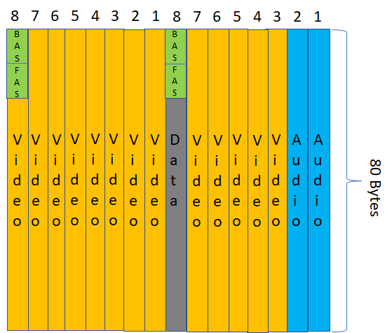
Figure 27: ITU Recommendation H.221
Let’s assume that we have 2 B channels at 64 kbit/s (Basic Access ISDN). H.221 creates on each B channel a Frame Structure of 80 bytes, i.e. 640 bits repeating itself 100 times per second. Each bit position in an octet can be considered as an 8 kbit/s sub-channel. The 8th bit in each octet represents the 8th sub-channel, called the Service Channel.
Within the Service Channel, bits 1-8 are used by the Frame Alignment Signal (FAS) and bits 9-16 are used by the Bit Alignment Signal (BAS). Audio is always carried by the first B channel, e.g. by the first 2 subchannels, and Video and Data by the other subchannels (less the bitrate allocated to FAS and BAS).
MPEG-1 Systems
The solution depicted in Figure 1 bears the mark of the transmission part of the telecom industry that had never been much friendly to packet communication. That is why MPEG in the late 1990’s had an opportunity to bring some fresh air in this space. Starting from a blank sheet of paper (at that time MPEG still used paper 😊) MPEG designed a flexible packet-based multiplexer to convey in a single stream compressed audio, video and clock information in such a way as to enable audio‑video synchronisation (Figure 28).
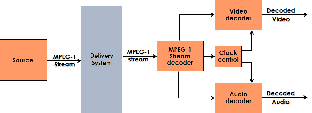
Figure 28: MPEG-1 Systems
The MPEG Systems revolution took time to take effect. Indeed, the European EU 95 project used MPEG-1 Audio layer 2, but designed their frame-based multiplexer for the DAB service.
MPEG-2 Systems
In the early 1990’s MPEG started working on another blank sheet of paper. MPEG had designed MPEG-1 Systems, but the MPEG-2 requirements were significantly different. While in MPEG-1 audio and video (possibly many of them in the same stream) had a common time base, the main users of MPEG-2 wanted a system that could deliver a plurality of TV programs, possibly coming from different sources (i.e. with different time bases) and typically with a lot of metadata related to the programs, not to mention some key business enabler such as conditional access information. Moreover, unlike MPEG-1 where it was safe to assume that the bits issuing would travel without errors from a Compact Disc to a demultiplexer, in MPEG-2 it was mandatory to assume that the transmission channel was anything but error-free.
MPEG-2 Transport Stream (TS) provides efficient mechanisms to multiplex multiple audio-visual data streams into one delivery stream. Audio-visual data streams are packetised into small fixed-size packets and interleaved to form a single stream. Information about the multiplexing structure is interleaved with the data packets so that the receiving entity can efficiently identify a specific stream. Sequence numbers help identify missing packets at the receiving end, and timing information is assigned after multiplexing with the assumption that the multiplexed stream will be delivered and played in sequential order.
The structure of the transport bitstream, organised in fixed-length packets of 188 bytes of which 184 bytes are used for the payload, is depicted in Figure 29.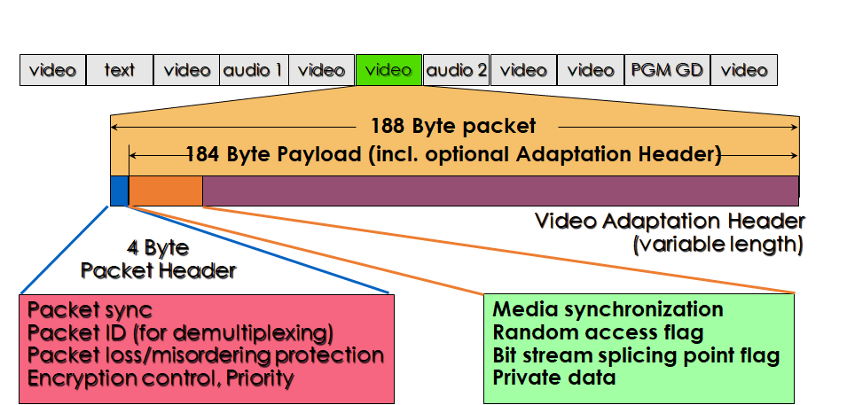
Figure 29 – The MPEG-2 packet format
Figure 30 shows thatMPEG-2 Systems is actually two specifications in one. The Transport Stream (TS) is a fixed-length packet-based transmission system designed for digital television distribution on error-prone physical channels, while the Program Stream (PS) is a packet-based multiplexer with many points in common with MPEG-1 Systems. `While TS and PS share significant common information, moving content from one to the other may not be immediate.
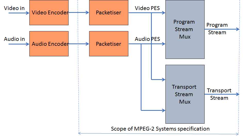
Figure 30: MPEG-2 Systems
MPEG-4 Systems
MPEG-4 gave MPEG the opportunity to experience an epochal transition in data delivery. When MPEG-2 Systems was designed, Asynchronous Transfer Mode (ATM) was high on the agenda of the telecom industry and MPEG considered it a possible vehicle to transport MPEG-2 TS streams on telecommunication networks. Indeed, the Digital Audio-Visual Council (DAVIC) designed its specifications on the assumption that MPEG-2 based Video on Demand services would be carried on ATM because at that time IP was still unknown to the telecom (at least to the transmission part), broadcast and consumer electronics worlds.
The MPEG-4 Systems work was a completely different story than MPEG-2 Systems. An MPEG4 Mux (M4Mux) was developed along the lines of MPEG-1 and MPEG-2 Systems. However, MPEG had to face an unknown world where many transports were surging as possible candidates. Today, 25 years later, the choice is clear, but at that time MPEG was unable to make choices – and it would not even be its task. Therefore MPEG developed the notion of Delivery Multimedia Integration Framework (DMIF), where all communications and data transfers between the data source and the terminal were abstracted through a logical API called the DMIF Application Interface (DAI), independent of the transport type: storage (local interactivity), network (remote interactivity) and broadcast (one way interactivity.
MPEG-4 Systems, however, was about more than interfacing with transport and multiplexing. The MPEG-4 model was a 3D space populated with dynamic audio, video and 3D Graphics objects. Figure 31 provides an example of MPEG-4 scene with 3D graphic objects and 2D video sprites.
Figure 31 – An example of MPEG-4 scene
Binary Format for Scenes (BIFS) was the technology designed to provide the scene description functionality, obviously in compressed form.
Figure 32 shows the 4 MPEG-4 layers: Transport, Synchonisation, Compression and Composition.
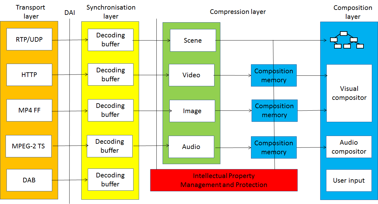
Figure 32 – MPEG-4 Systems
MPEG-4 File Format
For almost 10 years – until 1997 – MPEG was a group making intense use of IT tools (in the form of computer programs that simulated encoding and decoding operation of the standards it was developing) but was not an “IT group”. This can be seen from the fact that, until that time, it had not developed a single file format. Today MPEG can claim to have another such attribute (IT group) along with the many others it has.
In those years MP3 files were already being created and exchanged by the millions, but the files did not provide any structure, if not the one designed by the Audio group. The MP4 File Format, officially called ISO Base Media File Format (ISO BMFF), filled that gap as it can be used for editing, HTTP streaming and broadcasting.
Let’s have a high-level look to understand the sea that separates MP3 files from the MP4 FF. MP4 FF contains tracks for each media type (audio, video etc.), with additional information: a four-character the media type ‘name’ with all parameters needed by the media type decoder. “Track selection data” helps a decoder identify what aspect of a track can be used and to determine which alternatives are available.
Data are stored in a basic structure called box with attributes of length, type (expressed by 4 printable characters), possibly version and flags. No data can be found outside of a box. Figure 33 shows a possible organisation of an MP4 file
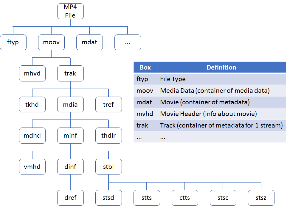
Figure 33: Boxes in an MP4 File
MP4 FF can store:
- Structural and media data information for timed presentations of media data (e.g. audio, video, subtitles);
- Un-timed data (e.g. meta-data);
- Elementary stream encryption and encryption parameter (CENC);
- Media for adaptive streaming (e.g. DASH);
- High Efficiency Image Format (HEIF);
- Omnidirectional Media Format (OMAF);
- Files partially received over lossy links for further processing such as playback or repair (Partial File Format);
- Web resources (e.g. HTML, JavaScript, CSS, …).
The first two features were in the original specification. The last two are still under development. All others were added in the years following 2001 when MP4 FF was approved.
MPEG-7 Systems
With MPEG-7, MPEG made the first big departure from media compression and turned its attention to media description including ways to compress that information. In addition to descriptors for visual audio and multimedia information, MPEG-7 includes a Systems layer used by an application, say, to navigate a multimedia information repository, to access coded information coming from a delivery layer in the form of coded descriptors (in XML or in BiM, MPEG’s XML compression technology). Figure 34 illustrates the operation of an MPEG-7 Systems decoder.
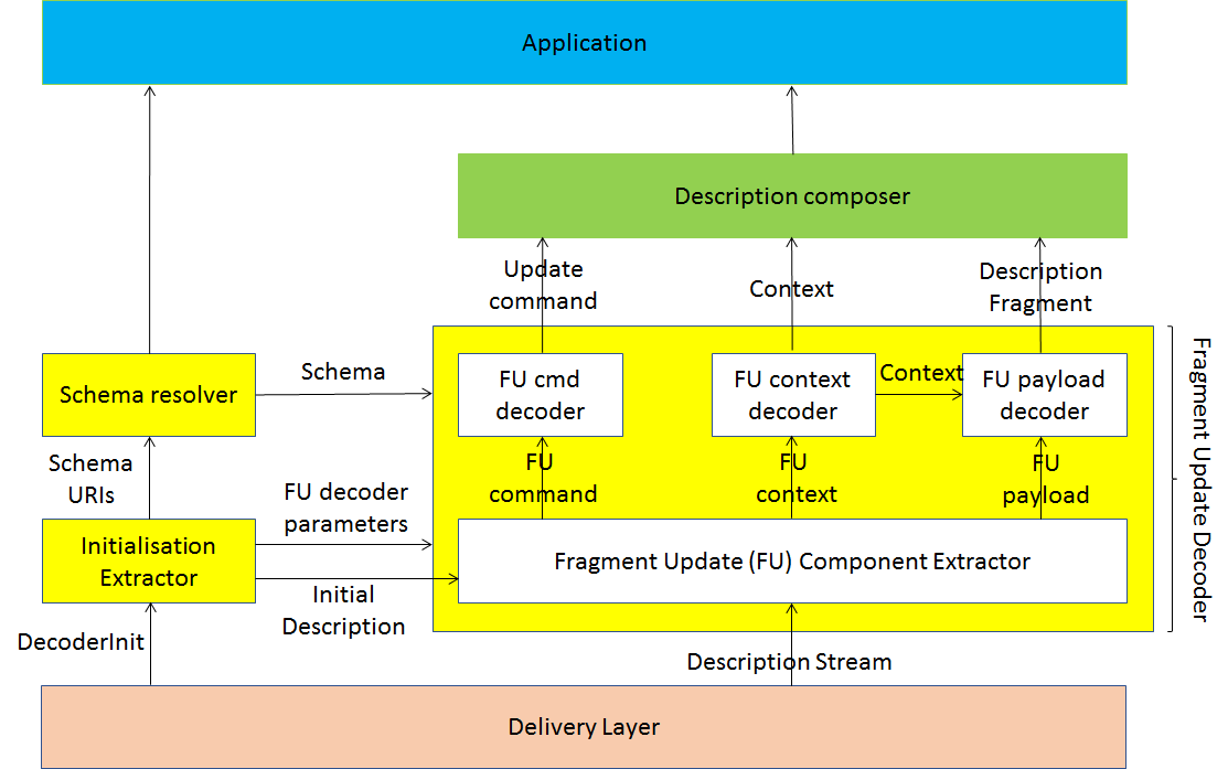
Figure 34: MPEG-7 Systems
An MPEG-7 Systems decoder operates in two phases
- Initialisation when DecoderInit initialises the decoder by conveying description format information (textual or binary), a list of URIs that identifies schemas, parameters to configure the Fragment Update decoder, and an initial description. The list of URIs is passed to a schema resolver that associates the URIs with schemas to be passed to Fragment Update Decoder.
- Main operation, when the Description Stream (composed of Access Units containing fragment updates) is fed to the decoder which processes
- Fragment Update Command specifying the update type (i.e., add, replace or delete content or a node, or reset the current description tree);
- Fragment Update Context that identifies the data type in a given schema document, and points to the location in the current description tree where the fragment update command applies; and
- Fragment Update Payload conveying the coded description fragment to be added to, or replaced in the description.
MPEG-E
MPEG Multimedia Middleware (M3W), also called MPEG-E, is an 8-part standard defining the protocol stack of consumer-oriented multimedia devices, as depicted in Figure 35.
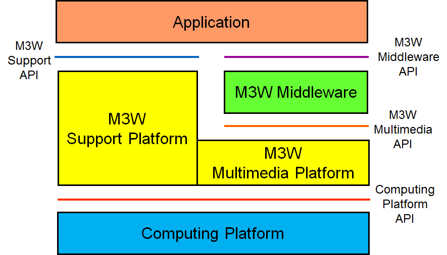
Figure 35: MPEG Multimedia Middleware (M3W)
The M3W model includes 3 layers:
- Applications: non part of the specifications but enabled by the M3W Middleware API;
- Middleware: consisting of
- M3W middleware exposing the M3W Middleware API;
- Multimedia platform supporting the M3W Middleware by exposing the M3W Multimedia API;
- Support platform providing the means to manage the lifetime of, and interaction with, realisation entities by exposing the M3W Support API (it also enables management of support properties, e.g. resource management, fault management and integrity management);
- Computing platform: whose API are outside of M3W scope.
MPEG-M
Multimedia service platform technologies (MPEG-M) is a 5-Part standard that specifies two main components of a multimedia device, called peer in MPEG-M.
As shown in Figure 36, the first component is API: High-Level API for applications and Low-Level API for network, energy and security.
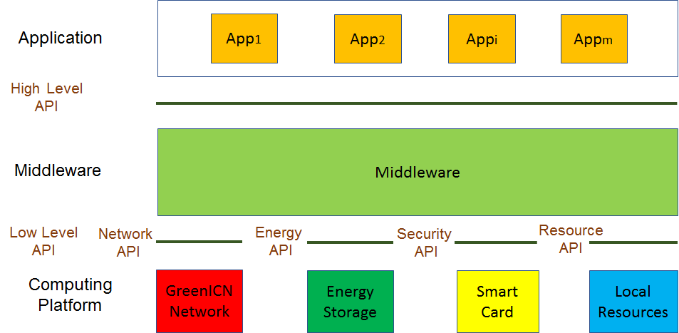
Figure 36: High-Level and Low-Level API
The second components is the middleware called MPEG eXtensible Middleware (MXM) that utilises MPEG multimedia technologies (Figure 37).
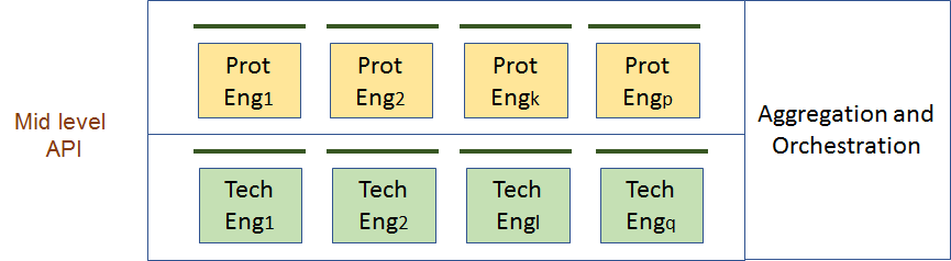
Figure 37: The MXM architecture
The Middleware is composed of two types of engine. Technology Engines are used to call locally available functionalities defined by MPEG standards such as creating or interpreting a licence attached to a content item. Protocol Engines are used to communicate with other peer, e.g. in case a peer does not have a particular Technology Engine that another peer has. For instance, a peer can use a Protocol Engine to call a licence server to get a licence to attach to a multimedia content item. The MPEG-M middleware has the ability to create chains of Technology Engines (Orchestration) or Protocol Engines (Aggregation).
MMT
MPEG Media Transport (MMT) is part 1 of High efficiency coding and media delivery in heterogeneous environments (MPEG-H). It is the solution for the new world of broadcasting where content can be delivered over different channels each with different characteristics, e.g. one-way (traditional broadcasting) and two-way (the ever more pervasive broadband network). MMT assumes that the Internet Protocol is the transport protocol common to all channels.
Figure 38 depicts the MMT protocol stack
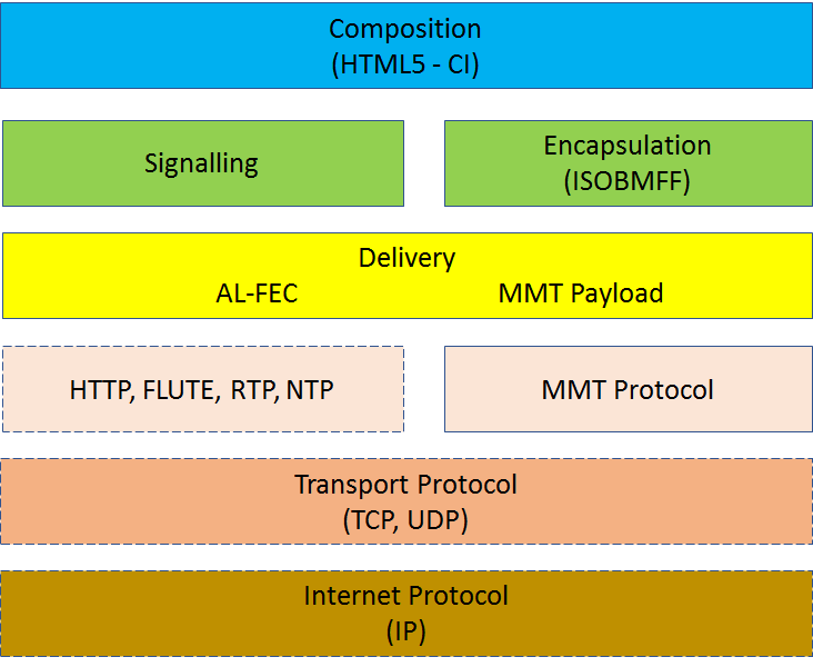
Figure 38: The MMT protocol stack
REF _Ref7105438 \h Figure 39 focuses on the MMT Payload, i.e. on the content structure. The MMT Payload has an onion-like structure. Starting from the inside:
- Media Fragment Unit (MFU), the atomic unit which can be independently decoded;
- Media Processing Unit (MPU), the atomic unit for storage and consumption of MMT content (structured according to ISO BMFF), containing one or more MFUs;
- MMT Asset, the logical unit for elementary streams of multimedia component, e.g. audio, video and data, containing one or more MPU files;
- MMT Package, a logical unit of multimedia content such as a broadcasting program, containing one or more MMT Assets, also containing
- Composition Information (CI), describing the spatio-temporal relationships that exists among MMT Assets;
- Delivery Information, describing the network characteristics.
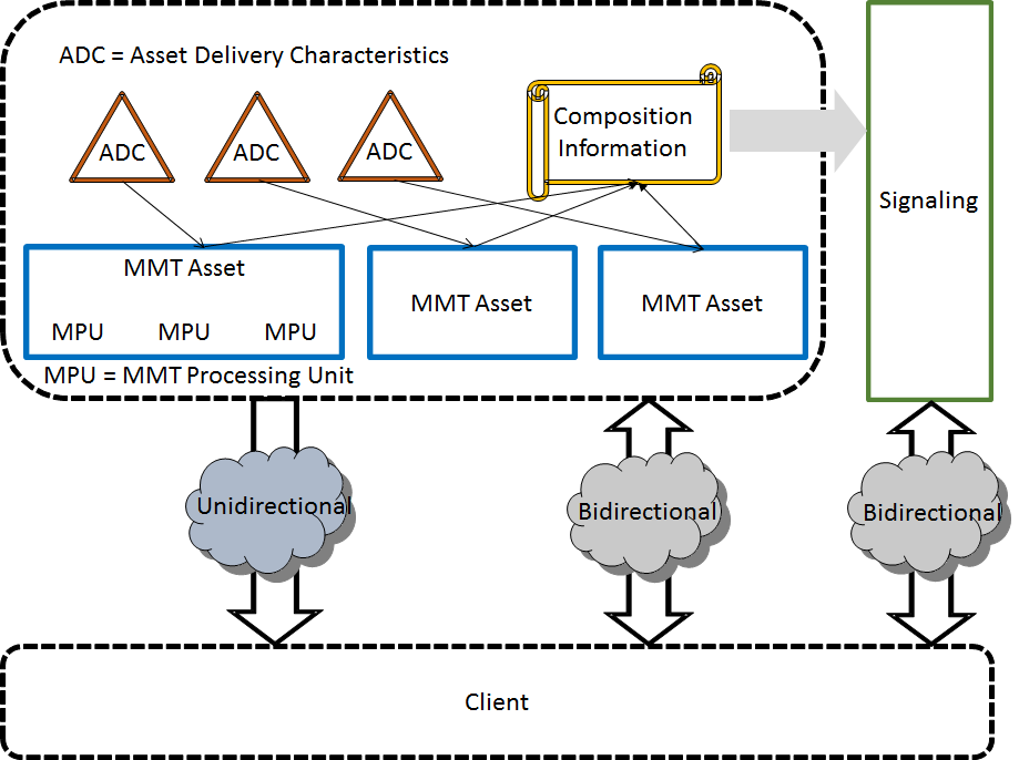
Figure 39: Structure of MMT Payload
MPEG-DASH
Dynamic adaptive streaming over HTTP (DASH) is another MPEG Systems standard that was motivated by the popularity of HTTP streaming and the existence of different protocols used in different streaming platforms, e.g. different manifest and segment formats. By developing the DASH standard for HTTP streaming of multimedia content, MPEG has enabled a standard-based client to stream content from any standard-based server, thereby enabling interoperability between servers and clients of different make.
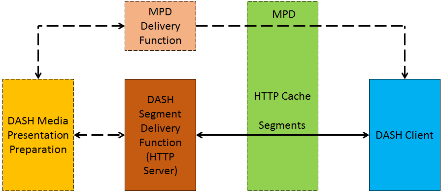
Figure 40 – DASH model
As depicted in Figure 40, the multimedia content is stored on an HTTP server in two components: 1) Media Presentation Description (MPD) which describes a manifest of the available content, its various alternatives, their URL addresses and other characteristics, and 2) Segments which contain the actual multimedia bitstreams in form of chunks, in single or multiple files.
A typical operation of the system would follow the steps
- DASH client obtains the MPD;
- Parses the MPD;
- Gets information on several parameters, e.g. program timing, media content availability, media types, resolutions, min/max bandwidths, existence of alternatives of multimedia components, accessibility features and the required protection mechanism, the location of each media component on the network and other content characteristics;
- Selects the appropriate encoded alternative and starts streaming the content by fetching the segments using HTTP GET requests;
- Fetches the subsequent segments after appropriate buffering to allow for network throughput variations
- Monitors the network bandwidth fluctuations;
- Decides how to adapt to the available bandwidth depending on its measurements by fetching segments of different alternatives (with lower or higher bitrate) to maintain an adequate buffer.
DASH only defines the MPD and the segment formats. MPD delivery and media encoding formats containing the segments as well as client behavior for fetching, adaptation heuristics and content playing are outside of MPEG-DASH’s scope.
Conclusions
This is not an exhaustive presentation of MPEG Systems work. Still the description will reveal the amount of work that MPEG has invested in Systems aspects, sometimes per se, and sometimes to provide adequate support to users of its media coding standards. Different standards compete for the palm of the most successful MPEG Systems standards. For sure the MPEG-2 Systems standard is a strong competitor: 9 editions have been produced to keep up with continuous user demands for new functionalities.
| Table of contents | ◄ | 10 Quality assessment | █ | 12 Data compression | ► |